555 Timer Circuit Schematic : Circuit Design And Technology: 555 TIMER AND CIRCUIT ... / You can either follow the previous schematic or follow the breadboard wiring diagram below.
555 Timer Circuit Schematic : Circuit Design And Technology: 555 TIMER AND CIRCUIT ... / You can either follow the previous schematic or follow the breadboard wiring diagram below.. The lm555 has a maximum typical supply voltage rating of 16v while the relay's armature coil is enabled at 12v. 555 timer ic remains in stable state until the external triggering is applied. The schematic is shown in fig 5. Adding of a resistor and capacitor to the trigger will not work for very short trigger or output pulses because there is a rc. This 555 timer is in astable mode.
The breadboard schematic of the above circuit is shown below. If once push button is pressed, it drives pin2 of timer the contact of the relay finally drives any external ac load. The circuit layout is for a 555 timer in astable mode. This is the schematic below for the 555 timer that creates one square wave output. Print the diagram in the centre of a sheet of paper create a circuit using the ics pin locations.
'555' Monostable Circuits | Nuts & Volts Magazine from www.nutsvolts.com The 555 can be used to derivatives provide two (556) or four (558) timing circuits in one package.2. Connect power and ground to pins 8 and 1 of the 555 timer (red and black wires). With this information you will learn how how the 555 works and will have the experience to build some of the circuits below. These fifteen 555 timer circuits are simple to make with widespread usability. Typical schematics in monostable operation. The standard 555 timer ic is used in a variety of timer, pulse generation and oscillator applications. The 555 timer ic is an integrated circuit (chip) used in a variety of timer, delay, pulse generation, and oscillator applications. The timer generates an output pulse with an on time period determined by the rc network i.e t = 1.1rc.
And now a full schematic of the 555 timer oscillator with single step and free run option.
The schematic shows (3) circuits, because one circuit does not work well over the entire vcc range. You can either follow the previous schematic or follow the breadboard wiring diagram below. The lm555 has a maximum typical supply voltage rating of 16v while the relay's armature coil is enabled at 12v. The 555 can be used to derivatives provide two (556) or four (558) timing circuits in one package.2. The 555 timer is a simple integrated circuit that can be used to make many different electronic circuits. Learn about the 555 timer and how it works in astable mode. Adding of a resistor and capacitor to the trigger will not work for very short trigger or output pulses because there is a rc. This tutorial provides sample circuits to set up a 555 timer in monostable, astable, and bistable modes as well as an in depth discussion of wiring info: The schematic is shown in fig 5. The breadboard schematic of the above circuit is shown below. A 555 timer is a very versatile. You can explore various applications based on monostable. Si notation all the schematics in this ebook have.
The 555 timer is configured as a monostable multivibrator. Si notation all the schematics in this ebook have. These fifteen 555 timer circuits are simple to make with widespread usability. You can explore various applications based on monostable. Since the project only involves assembling a simple circuit by following the schematic, it will only take an hour to make.
LM 555 Timer Circuit - ITCT from djckitct.weebly.com To observe the 555 timer in astable mode, let's build a circuit that uses the 555 timer's oscillating output to make. I used a 9v supply. The good thing is that this chip could work directly with 12v so no driver for the mosfet is needed. You can watch the following video or read the written tutorial below. Astable mode can produce digital square waveforms that go back and forth between. The 555 timer is a simple integrated circuit that can be used to make many different electronic circuits. This cycles 60 times every second. The 555 timer ic is an integrated circuit (chip) used in a variety of timer, pulse generation, and oscillator applications.
I used a 9v supply.
Astable mode can produce digital square waveforms that go back and forth between. This is the schematic below for the 555 timer that creates one square wave output. 555 timer ic remains in stable state until the external triggering is applied. The 555 and 7555 are called timers or timer chips. This cycles 60 times every second. The ne555, sa555, and se555 monolithic timing circuits are highly stable controllers capable of producing accurate time delays or oscillation. A 555 timer is a very versatile. Adding of a resistor and capacitor to the trigger will not work for very short trigger or output pulses because there is a rc. In this case, the fixed value of the capacitor is 100uf. This bistable configuration does not use any rc timing. We can see that it us made up of 21 transistors, 4 diodes, and 15. The 555 timer can provide time delays ranging from several minutes for one cycle of operation to many thousands of cycles per second. I used a 9v supply.
To make the same circuit as mentioned above without ic 555 timer, we will have to use the following basic electronic components and devices. The 555 timer ic is an integrated circuit (chip) used in a variety of timer, pulse generation, and oscillator applications. The breadboard schematic of the above circuit is shown below. The schematic is shown in fig 5. The 555 timer is a simple integrated circuit that can be used to make many different electronic circuits.
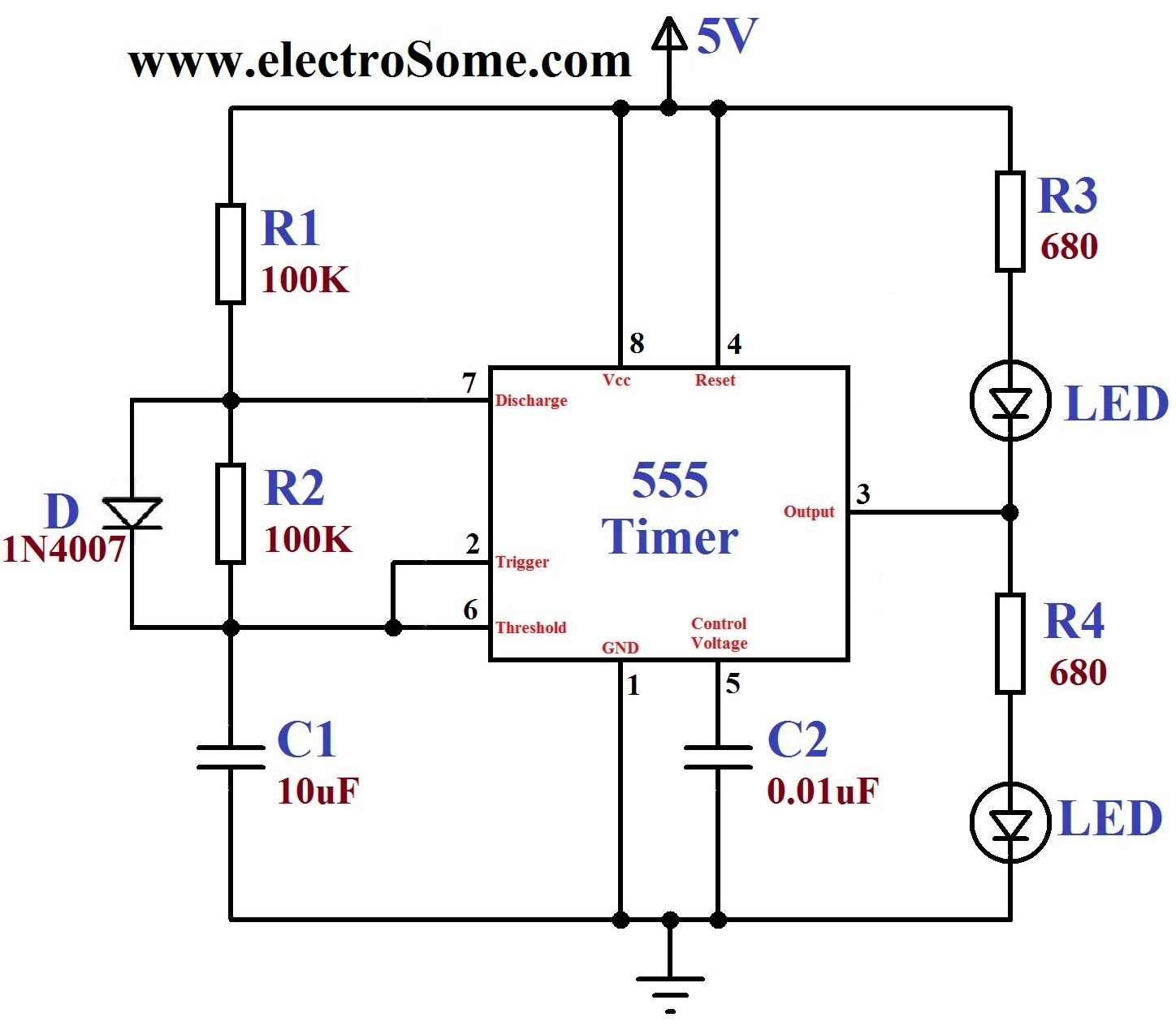
Dancing Light using 555 Timer from electrosome.com The 555 timer can provide time delays ranging from several minutes for one cycle of operation to many thousands of cycles per second. If once push button is pressed, it drives pin2 of timer the contact of the relay finally drives any external ac load. A 555 timer is a very versatile. The 555 and 7555 are called timers or timer chips. Si notation all the schematics in this ebook have. Look at the circuit diagram. In this case, the fixed value of the capacitor is. With this information you will learn how how the 555 works and will have the experience to build some of the circuits below.
The 555 timer can provide time delays ranging from several minutes for one cycle of operation to many thousands of cycles per second.
The red section is the. Print the diagram in the centre of a sheet of paper create a circuit using the ics pin locations. The circuit layout is for a 555 timer in astable mode. Before drawing the schematic, we need to create a library where we need to create and store the symbols for components. 7 below, you'll see the circuit schematic of the 555 and the parts relevant to it. The 555 and 7555 are called timers or timer chips. The standard 555 timer ic is used in a variety of timer, pulse generation and oscillator applications. The 555 timer is a simple integrated circuit that can be used to make many different electronic circuits. Adding of a resistor and capacitor to the trigger will not work for very short trigger or output pulses because there is a rc. These fifteen 555 timer circuits are simple to make with widespread usability. You can watch the following video or read the written tutorial below. Connect power and ground to pins 8 and 1 of the 555 timer (red and black wires). In this case, the fixed value of the capacitor is.
Above schematic diagram shows the 555 timer monostable multivibrator circuit 555 timer schematic. The 555 timer ic is an integrated circuit (chip) used in a variety of timer, pulse generation, and oscillator applications.


0 Komentar